
Industrial systems require precise pressure control to ensure optimal performance, safety, and equipment longevity. A pressure reducing valve serves as a critical component in maintaining consistent downstream pressure regardless of upstream fluctuations. These devices protect sensitive equipment, reduce energy consumption, and prevent costly system failures. Understanding the selection criteria for these valves can significantly impact operational efficiency and maintenance costs across various industrial applications.
Understanding Pressure Reducing Valve Fundamentals
Operating Principles and Mechanisms
The fundamental operation of a pressure reducing valve relies on balancing forces to maintain consistent downstream pressure. These valves utilize either spring-loaded diaphragms or piston mechanisms to respond to pressure changes automatically. When downstream pressure decreases below the setpoint, the valve opens wider to allow more flow. Conversely, when pressure exceeds the setpoint, the valve restricts flow to maintain the desired output pressure. This self-regulating behavior ensures stable operation without external control systems.
Modern pressure reducing valves incorporate advanced materials and precision manufacturing to achieve accurate pressure control. The internal components work together to create a feedback loop that continuously adjusts valve position based on downstream conditions. Temperature variations, flow rate changes, and upstream pressure fluctuations are compensated automatically through the valve's mechanical design. This reliability makes these devices essential for protecting downstream equipment and maintaining process stability.
Types and Configurations Available
Direct-acting pressure reducing valves represent the most common configuration for moderate flow applications. These units feature a simple spring-and-diaphragm design that responds directly to downstream pressure changes. Pilot-operated valves provide superior performance for high-flow applications or where precise control is critical. The pilot mechanism amplifies small pressure changes to control the main valve more effectively.
Specialty configurations include angle valves for space-constrained installations and multi-stage units for extreme pressure reduction requirements. Globe-style bodies offer excellent flow control characteristics, while angle designs minimize pressure drop and footprint requirements. The choice between bronze, stainless steel, or specialized alloy construction depends on media compatibility and environmental conditions. Each configuration offers specific advantages for particular applications and operating environments.
Critical Selection Factors for Industrial Applications
Flow Rate and Sizing Requirements
Proper sizing begins with accurate determination of maximum flow requirements under various operating conditions. The pressure reducing valve must handle peak flow demands while maintaining stable pressure control during low-flow periods. Undersized valves create excessive pressure drop and poor control response. Oversized units may exhibit instability and hunting behavior that affects system performance.
Flow coefficient calculations consider both the valve's inherent characteristics and installation conditions. Piping geometry, upstream pressure variations, and downstream load patterns influence sizing decisions. Professional sizing software or manufacturer guidelines help ensure optimal valve selection. The goal is achieving responsive pressure control across the entire operating range while minimizing energy losses and maintenance requirements.
Pressure Range and Accuracy Specifications
Operating pressure ranges must align with both upstream supply conditions and downstream system requirements. Standard residential units typically handle pressures up to 200 PSI, while industrial models accommodate much higher pressures. The pressure reduction ratio affects valve stability and control accuracy. Extreme reduction ratios may require multi-stage configurations or specialized high-performance designs.
Control accuracy specifications depend on downstream equipment sensitivity and process requirements. Standard valves achieve accuracy within plus or minus 10% of setpoint under steady conditions. Precision applications may require specialized units with enhanced accuracy specifications. Temperature effects on setpoint stability should be considered for environments with significant temperature variations. The relationship between accuracy requirements and valve cost guides the selection process for budget-conscious applications.
Material Selection and Compatibility Considerations
Body and Internal Component Materials
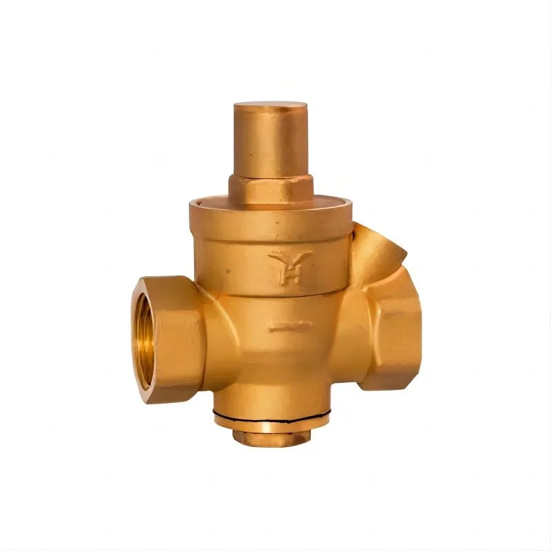
Bronze construction provides excellent corrosion resistance and durability for water and non-aggressive fluids. Brass components offer similar performance characteristics at lower cost for moderate-duty applications. Stainless steel bodies handle corrosive media and high-temperature applications where bronze alloys would degrade. The internal components including seats, springs, and diaphragms require compatible materials to ensure long-term reliability.
Specialized applications may require exotic alloys or coatings to handle aggressive chemicals or extreme temperatures. The media compatibility chart provided by manufacturers guides material selection for specific fluids. Galvanic corrosion between dissimilar metals in the system must be considered during material selection. Proper material choice prevents premature failure and ensures consistent performance throughout the valve's service life.
Environmental and Installation Factors
Ambient conditions significantly influence material selection and valve configuration choices. Outdoor installations require weather-resistant construction and may benefit from protective enclosures. Freezing conditions necessitate drain provisions or heating systems to prevent ice damage. High-temperature environments demand materials and seals rated for thermal cycling and extended exposure.
Installation orientation affects valve performance and accessibility for maintenance. Horizontal mounting generally provides optimal performance, while vertical installations may require special consideration for proper operation. Accessibility for adjustment and maintenance influences valve selection and installation planning. The pressure reducing valve location within the system affects both performance and maintenance requirements throughout its operational life.
Installation Best Practices and System Integration
Piping Layout and Flow Conditioning
Upstream piping configuration directly impacts valve performance and longevity. Sufficient straight pipe runs before the valve ensure developed flow patterns and minimize turbulence effects. Flow straightening vanes or conditioning plates may be necessary in complex piping systems. The valve should be installed with adequate clearance for maintenance access and pressure gauge installation.
Downstream piping design affects system stability and valve response characteristics. Excessive downstream volume can cause oscillation and hunting behavior. Proper support prevents piping stresses from affecting valve body alignment. Isolation valves upstream and downstream facilitate maintenance without system shutdown. Bypass arrangements provide operational flexibility and emergency backup capabilities when required by the application.
Monitoring and Control Integration
Pressure monitoring points provide essential feedback for system optimization and troubleshooting. Upstream and downstream pressure gauges enable performance verification and trend monitoring. Electronic pressure transmitters integrate with building automation systems for remote monitoring and alarm functions. Data logging capabilities support predictive maintenance programs and system optimization efforts.
Advanced control integration may include electric actuators for remote adjustment or automated setpoint changes. Pneumatic control systems provide precise positioning for critical applications. The integration complexity must balance functionality requirements against installation and maintenance costs. Simple mechanical adjustment remains appropriate for many applications where remote control is not required.
Maintenance and Troubleshooting Strategies
Preventive Maintenance Programs
Regular inspection schedules help identify potential issues before they cause system problems. Visual checks for external leakage, corrosion, and mechanical damage should be performed monthly. Pressure testing verifies continued accuracy and response characteristics. Internal inspection intervals depend on media quality, operating conditions, and manufacturer recommendations.
Preventive maintenance includes cleaning, lubrication, and component replacement as needed. Diaphragms and seals represent the most common wear items requiring periodic replacement. Spring tension verification ensures continued accurate pressure control. Record keeping supports trend analysis and helps optimize maintenance intervals for specific operating conditions. Proper maintenance significantly extends valve service life and maintains system reliability.
Common Issues and Diagnostic Approaches
Hunting or cycling behavior typically indicates oversized valves, insufficient downstream volume, or internal wear. Pressure testing isolates the root cause and guides corrective action. Failing to maintain setpoint pressure may result from worn internal components, contamination, or inadequate valve sizing. Systematic troubleshooting procedures help identify the specific cause efficiently.
External leakage usually involves seal or gasket deterioration that requires component replacement. Internal leakage affects pressure control accuracy and may indicate seat wear or contamination damage. Flow capacity reduction over time suggests internal fouling or component wear. Understanding these failure modes helps establish appropriate maintenance strategies and replacement schedules for optimal system performance.
FAQ
What is the typical service life of a pressure reducing valve in industrial applications
Industrial pressure reducing valves typically provide 10 to 15 years of reliable service when properly sized, installed, and maintained. Service life depends heavily on operating conditions, media quality, and maintenance practices. Valves handling clean water in stable conditions often exceed 20 years, while units processing contaminated or corrosive media may require replacement every 5 to 8 years. Regular maintenance including seal replacement and internal cleaning can significantly extend operational life.
How do I determine if my pressure reducing valve needs replacement or repair
Key indicators include inability to maintain setpoint pressure, excessive hunting or cycling behavior, visible external leakage, and significant changes in flow capacity. Pressure testing reveals control accuracy degradation and response characteristics. Internal inspection during routine maintenance shows component wear and contamination levels. Economic analysis comparing repair costs against new valve investment often favors replacement for older units or those requiring extensive internal work.
Can pressure reducing valves be installed in any orientation
Most pressure reducing valves are designed for horizontal installation with the bonnet oriented vertically upward for optimal performance. Some models accommodate vertical installation, but manufacturer specifications should be verified. Inverted installation is generally not recommended as it can trap debris and affect spring-loaded mechanism operation. Angle valves provide flexibility for space-constrained installations while maintaining proper internal component orientation.
What safety precautions are necessary during pressure reducing valve installation
System pressure must be relieved and lines drained before beginning installation work. Proper pipe support prevents stress on valve connections that could cause leakage or failure. Torque specifications for threaded connections prevent over-tightening damage to valve bodies. Pressure testing after installation verifies proper operation before returning the system to service. Personal protective equipment appropriate for the system media and pressure levels should always be used during installation and maintenance activities.
Table of Contents
- Understanding Pressure Reducing Valve Fundamentals
- Critical Selection Factors for Industrial Applications
- Material Selection and Compatibility Considerations
- Installation Best Practices and System Integration
- Maintenance and Troubleshooting Strategies
-
FAQ
- What is the typical service life of a pressure reducing valve in industrial applications
- How do I determine if my pressure reducing valve needs replacement or repair
- Can pressure reducing valves be installed in any orientation
- What safety precautions are necessary during pressure reducing valve installation